| | ULC-approved tank construction | Secondary containment | Location | Foundation and supports | Collision protection | Grounding for prevention of static electricity | Pumps, venting, valves, etc. | Emergency plan and equipment
When planning a petroleum storage site, there are many design criteria to consider. As mentioned in Section 3, the AFC provides a good set of guidelines for farmers to follow when designing a fuel storage system.
These guidelines include:
- ULC-approved tank construction
- Secondary containment
- Proper location
- Foundation and supports
- Collision protection
- Grounding for prevention of static electricity
- Pumps, venting, valves, etc.
- Emergency plan and equipment
This section will outline these design criteria in greater detail so that you can plan your own fuel storage site.
ULC-Approved Tank Construction
The Underwriters’ Laboratories of Canada (ULC) is an independent, not-for-profit product safety organization. A ULC-approved tank has been tested and approved for safety. In order to meet the AFC requirements, all petroleum storage tanks need ULC certification, indicated by a placard or sticker on the tank.

Figure 10. ULC Mark
Secondary Containment
Secondary containment is recommended to accommodate accidental spillage or leakage. The total capacity of the containment must be 110 percent of the maximum volume of the storage tank. If there is more than one tank, then the containment must hold 110 percent of the largest tank, or the capacity of the largest tank plus 10 percent of the total volume of the remaining tanks, whichever is greater.
Secondary containment can be achieved either by:
- Installing a double walled tank
- Using a diking system with an impermeable barrier or other premanufactured containment systems
A. Double walled tanks
Double walled tanks provide excellent protection against leaks, spills, and evaporation losses. These tanks have a built-in secondary containment which is the space between two walls that contain the fuel in the event of a leak or rupture of the interior wall. Some double walled tanks have a vacuum seal between the two walls with a pressure/inspection gauge that allows the owner to monitor the seal. If the interior wall produces a leak, the vacuum seal will be broken and will be indicated on the gauge. Other styles of double walled tanks allow the operator to visually inspect a chamber connected to an interstitial space.
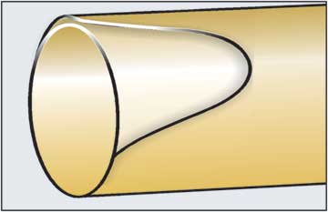
Figure 11. Diagram of double wall construction
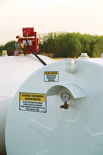
Figure 12. Double wall vacuum monitoring gauge
Photo courtesy of the Alberta Environmental Farm Plan, 2006
Double walled tanks can be equipped with an integral pump system providing excellent protection against leaks. The double walls provide some thermal insulation value reducing swings in fuel temperature. Installation is reduced to finding a suitable location, preparing a firm foundation and providing electrical power using wiring suitable for Class I hazardous locations. (refer to the Electrical Code). The fuel can be secured by shutting off the power to the pumps. The biggest drawback is the purchase price. This must be weighed against the advantages to determine if these tanks meet your needs. They are available in horizontal and vertical models.
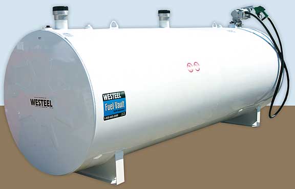
Figure 13. Double walled, on-ground tank (horizontal model)
Photo courtesy of Westeel
B. Diking with impermeable barrier or other premanufactured containment systems
An alternative to double walled tanks would be using a dike with an impermeable barrier or tub as secondary containment. Materials used should be non-combustible and impermeable such as compacted clay, concrete or steel with a liner made of a compatible synthetic material such as plastic. Earth dikes must have a flat top, not less than 600 mm (2 feet) wide and be at least 600 mm (2 feet) high.
The side slope should be natural for the material used. The floor of the containment must also be impermeable and sloped to a sump.
Since the containment is designed to hold 110 percent of the tank’s capacity, rainwater and other materials must be kept out or evacuated. If water has accumulated and is contaminated from minor leaks and spills, you can use a hydrocarbon absorbent (see Spill Kit section on page 28 in the Appendix) to absorb only the fuel and not the water. Then you can safely dispose of the fuel/absorbent and the clean water. Figure 14 shows an example of a suitable diking system.
An alternative that is available would be a premanufactured containment such as a tub, tray or a fully enclosed system, as illustrated in Figure 15.
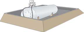 | 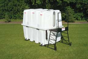 |
| Figure 14. On-ground tank with containment dike | Figure 15. Fully enclosed secondary containment system
Photo courtesy of Canadian Enviro-Tub Inc. |
Location
The proper location of a fuel storage system is very important in order to reduce the risk of fire, collisions, theft, and environmental impacts. The minimum separation distances from a petroleum storage tank are illustrated in Figure 16.
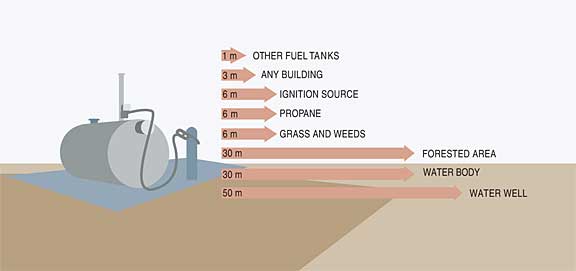
Figure 16. Minimum separation distances from petroleum storage
Foundation and Supports
When preparing a site for fuel tank storage systems, a solid foundation is important to prevent any uneven settling. Concrete, compacted clay or gravel are all good choices as material for the foundation. The foundation area should also be kept clear of weeds or other debris that may pose a fire hazard. See Figure 17 for an example of a suitable foundation and supports.
The metal stands typically used on many Alberta farms do not comply with the AFC. According to the AFC, all supports (except those less than 0.3 m high at their highest point) must provide a fire resistance rating of no less than 2 hours. The best practice is to mount at ground level or on solid concrete or steel supports no higher that 0.3 m (1 ft) off the ground.
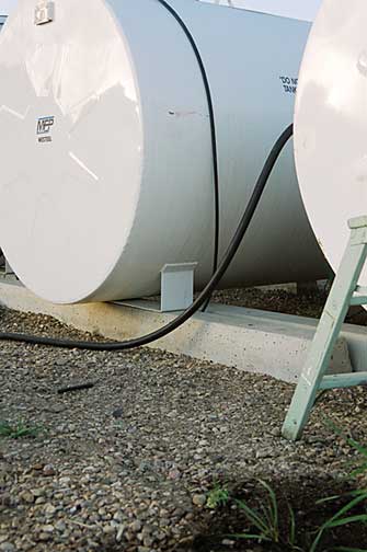
Figure 17. Double walled tanks using concrete supports on firm, compacted gravel
Photo courtesy of the Alberta Environmental Farm Plan Company, 2006
Collision Protection
The most common major leaks and spills are usually the result of vehicles or equipment colliding with petroleum tanks. For this reason, it is recommended that barriers be placed around the fuel storage site to prevent these accidental spills. The barriers can be in the form of bollards, or posts, either made of steel, concrete or heavy timber. Other effective ways to prevent collision with the tanks could include jersey barriers or large concrete curbs. Another example, as shown in Figure 18, is to use large boulders to protect the tank, providing a decorative feature as well.
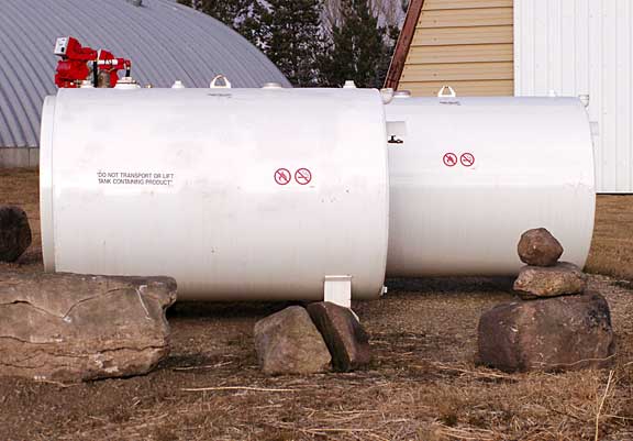
Figure 18. Collision protection using large boulders
Photo courtesy of MFP Mohawk Fuel Products Inc. and Scott Stack, 2006
Grounding for Prevention of Static Electricity
Static electricity can be a form of ignition. Two common causes of static electricity are the movement of grains though an auger and the movement of vehicles or machinery. Any time there is an imbalance in electrical charges between two objects, a spark can occur when they come in contact or close proximity. If the gasoline nozzle is the contact point between the fuel storage tank and a static-charged vehicle or farm machine, a spark may ignite any fuel vapours present. It is recommended that a bonding line be connected between the storage tank and the vehicle before the dispensing process has begun (Figure 19). A flexible, copper conductor, 12 gauge or larger, is recommended.
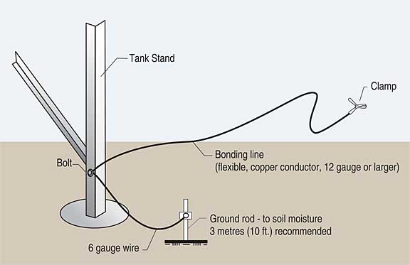
Figure 19. Bonding line and proper grounding of fuel tank supports
Pumps, Venting, Valves, etc.
Ensure pumps and meters are ULC approved and suitable wiring is used (for Class I hazardous locations, as outlined in the Electrical Code). Venting is an important aspect of proper fuel storage as well to prevent the build of pressure in the tank. The risk of accidental spills and leaks can be greatly reduced by the installation of ULC and CSA approved dispensing units and automatic shut off valves.
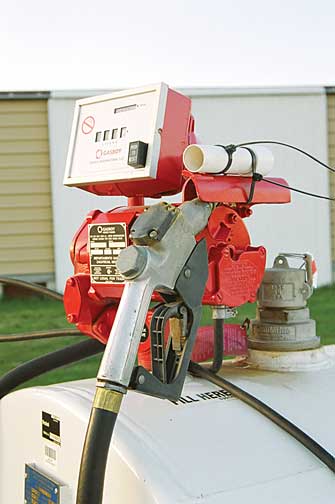
Figure 20. ULC approved pump and meter
The use of anti-siphon valves is also recommended. Installed between the pump and tank, these valves prevent the tank from draining if the line is broken. Lines are commonly broken in the event of a collision with the pump. Another recommendation is to use a valve equipped with a fusible link. In the case of fire, the link melts, closing the valve and shutting off the flow of fuel.
Emergency Plan and Equipment
An emergency plan consists of the identification and location of hazardous materials, emergency equipment, telephone numbers and necessary clean-up methods. This plan gives the residents of the farmstead guidelines for minimizing potential environmental damage to the site, as well as protecting themselves and the surrounding community. Emergency response teams should also have access to the plan to help them distinguish between response procedures for different situations. For more information on creating an emergency plan, refer to the Appendix.
Source: Agdex 769-1. September 2008. |
|