| | Introduction | Number and location of monitoring wells | Drilling and logging boreholes | Monitoring well construction and installation | Monitoring well protection | Use of cement | Monitoring well development | Groundwater level measurement | Surveying | Documentation | Professional qualifications | References | Appendix 1 – additional information | Appendix 2- classification systems of sediment size
Purpose
- To guide the construction, installation and development of groundwater monitoring wells
Audience
- Consultants or contractors hired to construct, install, and develop groundwater monitoring wells at confined feeding operations (CFOs)
Relevant Legislation
- Agricultural Operation Practices Act
Risks Addressed
- Ensure representative groundwater samples
- Prevent contaminated surface water from reaching groundwater through the well space
- Prevent groundwater movement and transfer between aquifers
- Prevent improper construction or installation of groundwater monitoring wells. Improperly constructed or installed wells may need to be reclaimed or replaced, resulting in significant additional costs
Introduction
This guideline outlines recommended and preferred protocols to construct, install and develop groundwater monitoring wells at confined feeding operations (CFOs), which are regulated under the Agricultural Operation Practices Act (AOPA). Materials and methods presented are preferred and acceptable for typical situations. Other methods and materials may be acceptable under specific situations, based on the judgment of qualified professionals. Monitoring wells must be constructed, installed and developed by knowledgeable and experienced individuals under the guidance of a suitably qualified professional.
Groundwater monitoring refers to the monitoring of local groundwater resources to evaluate changes in chemical, biological and physical characteristics. It includes periodic sampling and analysis to detect changes in constituents in groundwater and periodic measurement of water levels to determine the direction of groundwater flow. To be effective, groundwater monitoring wells should be constructed and installed using methods and materials that minimize the effects on the chemical, biological and physical properties of groundwater samples. Monitoring wells should permit representative groundwater sampling, accurate measurement of groundwater elevation and in-situ hydraulic conductivity testing.
Number and Location of Monitoring Wells
The number and location of groundwater monitoring wells should be determined before decisions are made regarding the materials and methods for constructing and installing the wells. A hydrogeological assessment should be the basis for determining the number and location of monitoring wells.
The NRCB must be contacted in order to receive approval before groundwater monitoring wells are constructed and installed. The NRCB will evaluate the proposed monitoring plan and, based on the perceived risk of potential leakage of the facility and the perceived risk to the environment, may require modifications to the plan. If monitoring wells are installed and constructed without NRCB approval, there is a risk that the well will not be approved and that new or additional wells will be required.
Drilling and Logging Boreholes
A variety of borehole drilling methods may be appropriate depending on the geology and characterization of each site. The method used should be determined by the qualified professional responsible for installing the monitoring well(s). Common methods are discussed in Appendix 1.
- Lithologic Log
During drilling, geologic descriptions should be logged continuously and directly from drilling returns. The lithologic log should be recorded by a qualified individual using either the Canadian System of Soil Classification (NRC, 1988), the Unified Soil Classification System (ASTM, 2006) or the Wentworth scale (1922). There are significant differences in how the three systems describe texture or grain size. The system or combination of systems used must be specified on the drill or borehole logs, and must be used consistently for the site (see Appendix 2).
The lithologic log should include a description of soil texture (clay, silt, sand, gravel) or lithology (for example sandstone, siltstone, claystone, coal), grain size, colour, moisture content, consistency, hardness, and secondary features such as staining, mottling, carbonates, gypsum, degree of cementation, degree of weathering and odour. The lithologic description should also include the presence or absence of visible fractures as indicated in core or split-spoon samples, or surface staining on rotary cutting returns.
- Representative Samples
Representative samples of sediments encountered during drilling must be collected for at least every 1.5 metres of drilling, or where changes in lithology are suspected or observed.
- Decontamination of Equipment
Decontamination of drilling and formation sampling equipment is a quality control measure that is included as part of standard drilling procedures. It is important for preventing cross contamination between sampling areas. The professional responsible for the drilling and sampling should evaluate the decontamination requirements for each site. Although decontamination is typically used where contamination is present, it may also be used in uncontaminated areas as a quality control and assurance measure.
Monitoring Well Construction and Installation
- Materials
Monitoring wells are constructed of environmental quality threaded PVC pipe, 52 millimetre ID Schedule 40, with a machine slotted 3.0 metres long or 1.0 to 1.5 metres long, 0.020 or 0.010 slot screen. A 3.0 metre screen would typically be used for relatively shallow intervals. A 1.0 to 1.5 metre screen would typically be used for relatively deeper intervals. Longer screens may be required, depending on the borehole depth and stratigraphy of the site. The length of the screen selected depends on the thickness of the hydrogeologic unit, the vertical scale of the investigation, and specific requirements of the monitoring program. For typical water table monitoring wells, a screen 3.0 metres long is common. The screen must not extend to within less than two metres of the ground surface to allow for an adequate length of bentonite seal above the screen.
- Joints
The 52 millimetre PVC screens and all plain pipe sections must have threaded flush joints with
O rings or Teflon tape at the joints. Solvent welded PVC pipes, screens and couplings should not be used to construct monitoring wells. PVC glue and primer can potentially introduce organic substances into the monitored environment. Screen bottoms must be closed with a heat welded seal or threaded end cap.
- Size of Boreholes
Groundwater monitoring well components are placed in each borehole. Boreholes must be at least 102 millimetres (approximately four inches) larger than the outside diameter of the casing and screen. For instance, when a 52 millimetre (two inch) well casing is used, the drill borehole diameter should be at least 154 millimetres (approximately six inches). This ensures adequate space around the well screen and casing, which allows for proper placement of completion materials such as filter sand and bentonite, and helps prevent materials from bridging between the casing and borehole walls.
- Borehole Backfill
The annular space between the screened section of the monitoring well and the borehole wall is backfilled with filter sand, typically 10/20 mesh (2.0 to 0.84 millimetres) fraction silica sand. Environmental silica sand is used because it does not contribute significant soluble ions to the groundwater. Sand of mixed lithologies may contain minerals that could affect trace element concentrations in monitored groundwater, and is not recommended. The filter sand is placed to approximately 0.3 metres above the top of the monitoring well screen to accommodate settling, and to prevent contact between the bentonite seal (described below) and the well screen. As the sand is placed in the borehole, the depth of filter sand pack is sounded with a weighted tape measure to ensure correct placement without bridging.
- Borehole Sealing
The annular space above the sand pack, refered to as the annulus, must be sealed to prevent surface water or shallow groundwater from moving through it. A primary, water tight bentonite seal, approximately 0.3 metres thick, is placed above the sand pack using bentonite pellets. Bentonite chips are not recommended for the primary seal. If bentonite chips are used for the primary seal, extra care must be taken to ensure that bridging does not occur if water is present in the borehole.
To ensure hydraulic isolation between the ground surface and other potential water-bearing horizons, the entire remaining annulus must be backfilled to ground surface with hydrated bentonite chips. Cuttings should never be used to fill the annulus.
While bentonite chips are being placed in the annulus, the depth of the bentonite chips must be sounded with a weighted tape measure to ensure correct placement of the seal, without bridging in the hole.
The bentonite chips must be hydrated, by adding approximatively seven litres of fresh, potable water per 20 kilograms of chips after each bag is placed.The type and depth of backfill material should be noted on the well construction log.
The top of the monitoring well must be capped with a snug fitting or threaded PVC cap. A small vent hole or slot should be drilled or cut below the bottom of the cap to allow air movement in and out of the monitoring well to allow water levels to fluctuate properly.
Monitoring Well Protection
The monitoring well must be completed at the surface with a steel protective steel surface casing, which has a lockable cover or some other protective device to prevent damage or tampering. The protective steel surface casing should be approximately 1.5 metres long and 141 millimetres in diameter, and must be installed around the PVC pipe to approximately 0.75 metres below ground surface into the borehole.
A surface mound around the monitoring well is required. The mound should be comprised of compacted soil, clay or bentonite and be placed around the casing to move surface water away from the well.
Use of Cement
Cement should not be used for any part of the monitoring well construction and installation. Cement creates the potential for frost heave, other frost action and cracking. Frost damage may cause vertical displacement of the well and may shatter and fracture the seals and aprons around the wells. Any cement that is in close proximity to the screen or sand pack may also compromise the chemical quality of water in monitoring wells. If cement has been used to install the security casing around the monitoring well, the annular space between the security casing and the monitoring well should be filled with bentonite, not cement.
Monitoring Well Development
Groundwater monitoring wells are developed to clear the wells of fine sediment, reduce the effects of possible wall smearing as a result of the drilling process, and restore the water producing zone of the screened section to its original condition. Development is typically accomplished by removing water from the well with a bailer or pump. A minimum of three full well volumes should be removed. Additional purging may be required, depending on the individual well and soil characteristics. An example of this is when a well is still producing a large amount of sediment after the three volumes have been removed. Development is typically done once, soon after the well is installed, but before the first samples are taken.
Groundwater Level Measurement
Groundwater levels are measured and reported following well development and once the water level in the monitoring wells has stabilized. This typically occurs within one to several days after installation. In fine textured soils it may take groundwater levels several weeks or months to stabilize. In coarse textured materials, groundwater levels can stabilize within minutes.
Groundwater levels in monitoring wells should be measured using an electric sounding tape. The measurements must always be made from a known fixed reference point, typically the top of the well casing. The sounding tape should be rinsed with distilled or demineralized water before and after each measurement.
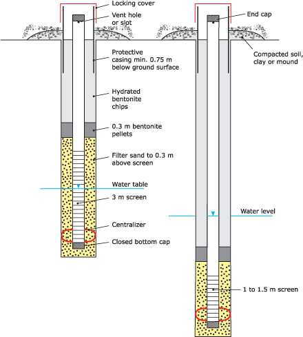
Figure 1. Typical construction of shallow and deep monitoring wells
Surveying
Groundwater flow direction is determined using information about the locations and elevations of the monitoring wells.
- Elevation
The elevation of the monitoring wells should be surveyed relative to a common datum or reference point. A local datum is suitable. This provides the relative elevation of the monitoring wells to each other. The difference between the groundwater elevations indicates flow direction. The top of the well casing is the most reliable point for the elevation survey, given that the height of the well casing above ground surface, commonly called stick up, is measured. Ground surface is typically not an accurate basis for the elevation survey.
The relative elevations of the monitoring wells must be accurate to within 0.25 centimetres, as the difference in groundwater elevation across a site may only be a few centimetres. Consequently, some surveying methods, such as common global positioning system (GPS) techniques, are not suitable for establishing the relative elevation of monitoring wells.
- Spatial Location
The spatial location of the monitoring wells is also required. Although an accurate survey is preferable, the locations of the monitoring wells can be measured from a known reference point at each site. The location of the wells should be accurate to within a few metres, depending on the size of the facility and monitoring well spacing. Most GPS methods are suitable for determining monitoring well location. As with elevation, it is the relative location of the monitoring wells to each other and to the manure storage facilities and other site features that is required. Real world coordinates (referenced to established topographic maps) are not required, but can be helpful if the site needs to be mapped relative to larger scale features or receptors.
Documentation
- Borehole
A borehole log must be prepared for each groundwater monitoring well, showing the lithologies encountered, depth drilled and completion details. (See section on drilling and logging boreholes).
Borehole logs should include both a graphical and textural description of sediments encountered at each monitoring well location, completion details and key features.
- Monitoring Well Completion
The summary table of monitoring well completion information should include, at a minimum, the following information:
- Ground surface elevation (relative or geodetic)
- Top of well casing elevation (relative or geodetic)
- Height of casing stick up, above ground surface
- Total depth of monitoring well
- Diameter of borehole
- Screened interval and sand packed interval (depth below ground surface)
- Spatial location of monitoring wells
- Documentation of type, specifications and placement of all material (e.g. filter pack, casing, screen, bentonite seals)
- Development details (method used and volume of water removed)
- Groundwater level (depth below top of casing and ground level)
Professional Qualifications
Groundwater monitoring wells must be constructed, installed and developed by knowledgeable and experienced individuals under the guidance of a suitably qualified professional.
References
American Society for Testing and Materials (ASTM). 2006. Standard Practices for Classification of Soils for Engineering Purposes (Unified Soil Classification System). D 2487-06.
Komex Consultants Ltd. 1983. Design and Construction of Liners for Municipal Wastewater Stabilization Ponds. Prepared for Alberta Environment, Municipal Engineering Branch, Edmonton, Alberta.
National Research Council of Canada (NRC). 1988. The Canadian System of Soil Classification (third edition). Soil Classification Working Group. NRC Press, M-55. Agriculture and Agri-Food Canada Publication 1646.
Wentworth, C.K. 1922. “A scale of grade and class terms for elastic sediments.” Journal of Geology 30: 377-392.
Appendix 1 – Additional Information
Typical borehole drilling methods
A truck mounted auger drilling rig is typically used for monitoring well installations, though various methods are available depending on site geology and characterization requirements. Auger rigs are well suited to drilling in fine to medium grained unconsolidated materials, or poorly consolidated bedrock.
Solid stem auger drilling can be used for shallow and deeper well completions in competent unconsolidated materials in which the borehole stays open and does not slough. Logging of the geologic material is accomplished by describing cuttings on the auger flights at regular intervals.
Hollow stem auger drilling is typically used if there are unstable borehole conditions, for example, saturated sand, in the shallow zone or completion zone or if substantial contamination is evident in the shallow zone. Hollow stem augers provide a temporary casing to support the borehole walls as drilling advances, minimizing the potential for shallower geologic materials to enter the borehole. Samples are commonly collected using a split-spoon sampler (coring tube), typically 45 to 60 centimetres in length, or other suitable coring devices.
Rotary drilling methods may be necessary for monitoring well installation when drilling into hard, competent bedrock sediments (for example sandstone, siltstone or shale). Rotary drills down the drill stem and up the annular space of the borehole to lubricate the drill bit and carry drill cuttings to the ground surface. Air rotary drilling uses compressed air to accomplish the same function. Air circulating rotary drilling is preferred over mud rotary. Air rotary drilling poses less risk of contaminating porous or fractured sediments in which a monitoring well is being installed.
In boreholes drilled with rotary drill methods, the screened zone should be cleaned and flushed with clean water to remove any drilling dust, debris (air rotary), or drilling fluid that may have coated the borehole walls (including pores, fractures, or other voids in the completion zone) before any of the components (filter sand, screen, etc.) of the monitoring wells are installed. This is necessary to ensure that good hydraulic connection in the monitoring zone is established and that water levels are able to fluctuate freely, and remove potential contamination.
Prevention of bridging
Centralizing devices may be installed in monitoring wells to overcome potential bridging problems. One centralizer should be installed at or below the bottom of the screen and unless it is expected that bridging problems with the filter sand may arise, a second centralizer should be installed above the top of the screen.
Centralizers also prevent the sides of the screen from contacting the borehole walls during installation, preventing smearing or clogging of the screen as it is lowered and installed through wet, clay rich materials. In the case of hollow stem drilling, the PVC screen and pipe are installed through the auger stem to the desired depth and centralizers are not required.
Appendix 2- Classification Systems of Sediment Size
Three classification systems are commonly used in Canada to describe and classify materials which make up unconsolidated and consolidated bedrock sediment. These classifications are the Unified Soil Classification System (ASTM),1 the Canadian System of Soil Classification (NRC)2 and the Wentworth scale.3 See Table 1, below, for a comparison of these three systems.
Table 1. Nomenclature and particle size used by common classification systems
| Nomenclature (all units in mm) | NRC | ASTM | Wentworth |
| Boulder |  | >300 | >256 |
| Cobble | | 75 - 300 | 64 - 256 |
| Very coarse gravel | | | 32 - 64 |
| Coarse gravel | | 19 - 75 | 16 - 32 |
| Medium gravel | | | 8 - 16 |
| Fine gravel | | 4.75 - 19 | 4 - 8 |
| Very fine gravel | | | 2 - 4 |
| Very coarse sand | 1 - 2 | | 1 - 2 |
| Coarse sand | 0.5 - 1 | 2 - 4.75 | 0.5 - 1 |
| Medium sand | 0.25 - 0.5 | 0.425 - 2 | 0.25 - 0.5 |
| Fine sand | 0.10 - 0.25 | 0.075 - 0.425 | 0.125 - 0.25 |
| Very fine sand | 0.05 - 0.10 | | 0.0625 - 0.125 |
| Silt | 0.002 - 0.05 | <0.075 | 0 0039 - 0.0625 |
| Clay | <0.002 | | <0.0039 |
| Colloid | <0.0002 | | <0.001 |
1. Unified Soil Classification System (ASTM), D 2487-06
2. Canadian System of Soil Classification (NRC), 1988
3. Wentworth Scale, 1922
The NRC System was developed to allow descriptions of soil properties and classification by soil scientists. The ASTM System focuses on describing engineering properties of earth materials. The Wentworth scale is used primarily by geologists to describe and classify sediments based on grain size, and is more suited to geologic and hydrogeologic characterization of sediments.
Table 1 shows that the three size classification systems differ from each other in significant ways. The NRC System does not describe grain sizes larger than coarse sand. The ASTM System classifies grain sizes differently than either the NRC or Wentworth systems. Both the NRC and Wentworth systems define the largest grain size diameter as two millimetres, whereas the ASTM System defines sand as a grain size as large as 4.75 millimetres.
For more information
Contact your nearest NRCB field office or an AF Agri-Environmental Extension Specialist (dial 310-0000 to be connected toll free)
Alberta Agriculture and Forestry
www.agriculture.alberta.ca/aopa
Ag Info Centre 310 FARM (3276)
Publications (780) 427-0391
Natural Resources Conservation Board
www.nrcb.ca
Fairview - closed, please contact Morinville.
Morinville (780) 939-1212
Red Deer (403) 340-5241
Lethbridge (403) 381-5166
This guideline was developed by the Technical Advisory Group, a partnership between Agriculture and Forestry, the Natural Resources Conservation Board and the agricultural industry.
Source: Agdex 096-51. January 2018. |
|