| | Operation | Application | Limitations | Maintenance | Priming
Deep well jet pumps are usually for wells with a pumping lift of 22 to 120 feet (Figure 1). A deep well jet pump combines two principles of pumping – that of the centrifugal pump and that of an injector (nozzle and venturi assembly).
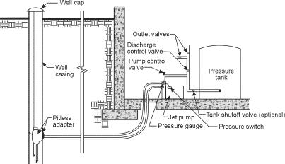
Figure 1. Deep well jet installation
Operation
The pump and pipe system are full of water. The water in the pump impeller is thrown outwards by the vanes of the spinning impeller (see insert detail Figure 2).
As the vanes throw the water out, a vacuum is created at the eye of the impeller, and more water is drawn in to replace that which was thrown out. Some of the water discharged by the impeller passes out of the pump and into the pressure tank. The rest is recirculated through the drive line to the injector in the well.
In the injector, the nozzle and the venturi create a vacuum. This vacuum draws water from the well, through the foot valve. As the water passes through the venturi tube into the suction line, the pressure is increased sufficiently to force the water back to the pump impeller.
The injector nozzle and venturi tube size must be selected according to the pumping depth, the distance the pump is offset from the well and the size of the pump. All pump companies provide charts for proper pump and injector selection. Because of the amount of water being circulated in this type of pumping system, it is important that the proper sizes of suction and drive lines are used to maximize efficiency.
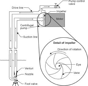
Figure 2. Deep well jet pump operations
Application
Deep well jet pumps:
- can be offset from the well
- can be adapted to wells of various depths and yields
- are relatively trouble-free if properly selected, installed and adjusted
- can be primed on long offsets through uneven terrain
- are relatively inexpensive
Limitations
Pumping abrasives, such as sand, will wear the impeller and can wear the mechanical seals causing leaking around the pump shaft.
Deep well jet pumps become less efficient as pumping lift increases. For lifts greater than 80 feet, submersible pumps may be preferred if the well yields sufficient sand-free water. Jet pumps are relatively inefficient at pumping water containing air or gases.
Jet pumps will lose their prime if the water level in the well drops below the foot valve. This result can be prevented in a slow yielding well by using an automatic pressure regulator and a weak well tailpipe below the injector (Figure 3). This tailpipe system will automatically adjust the pumping rate to the well capacity. The mechanical seal on the pump shaft is water lubricated and water cooled, so the pump should never be run without the pump casing being filled with water.
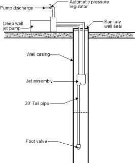
Figure 3. Tailpipe assembly
Maintenance
No regular maintenance is required on jet pumps. However on new installations, the nozzle may become partially or completely plugged with dirt or plastic scraps. When this blockage occurs, the pump may lose its prime, pump below capacity, fail to build pressure or be impossible to prime to begin with. Encrusting waters may cause mineral deposits to build up on metal components. These deposits can break loose and plug the injector nozzle, requiring the jet assembly to be pulled from the well and cleaned.
Priming
Short offset
- Fill suction and drive lines with water and connectto pump.
- Fill pump casing with water.
- Replace priming plug, do not tighten.
- Close pump control valve.
- Start the pump (air will bubble around priming plug).
- When bubbling stops, stop the pump. Refill the pump casing. Repeat Step 5.
- When the pump is primed, water will flow continuously under pressure around the priming plug, which should then be tightened.
- Adjust the pump control valve so the pump does not produce faster than the safe yield of the well.
- If a precharged type pressure tank is used, see Agrifacts 716(C31) Pressure Tanks for precharging the tank.
Long offsets
- Connect drive line to the pump.
- Temporarily connect a short length of pipe with a foot valve to the suction tapping of the pump. Submerge the foot valve in a tub of water.
- The suction line from the injector is directed to return the water flow to the tub.
- Close pump control valve. Fill the pump casing with water.
- Start the pump (water will be drawn from the tub and forced down the drive line).
- Add enough water to the tub to keep the foot valve submerged.
- When the pump begins to add more water to the tub than is being pumped out, stop the pump.
- Disconnect the short temporary suction line and connect the regular suction line to the pump. Fill the pump casing with water.
- Start the pump. Open the pump control valve slowly. Operate until all air pockets have been worked from the system.
- Adjust the pump control valve so the pump cannot produce faster than the safe yield of the well.
- If a precharge type pressure tank is used, see Agrifacts 716(C31) Pressure Tanks for precharging the pressure tank.
For more information
Alberta Ag-Info Centre
Call toll-free: 310-FARM (3276)
Website: www.agriculture.alberta.ca
Prepared by
Alberta Agriculture and Rural Development
Source: Agdex 716(C11). Revised March 2008. |
|