| | Electric fence operation | Fence design and construction | Energizers
Landholders who store livestock or cervid feed and bedding occasionally suffer substantial losses due to the feeding haqbits of wild ungulates such as deer and elk during winter. Depredation of hay and greenfeed bales by elk is worst when snowfall occurs early and the snow is deep. Fencing hay yards with 2.1 m high mesh wire has been an effective, but expensive, way to keep elk away from stored hay. A more economical way to prevent elk and deer damage employing electrified fencing is being used by farmers in British Columbia.
To test the effectiveness of this kind of fencing in Alberta, a test electric fence was built around a one acre hay yard near Niton Junction. Elk had been responsible for serious hay depredation at the farm in the previous winter. Elk were unable to penetrate the electric fence (Figure 1). Not only was the fence effective, but the electric fence cost much less to build than a comparable fence using barrier mesh. The material cost for building an electric fence is about half the cost of a mesh fence.
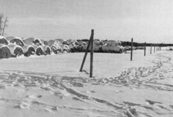
Figure 1. Elk tracks by the electric fence.
Electric fence operation
Electricity will only flow through a circuit that is uninterrupted. In the case of an electric fence, the electrical current must travel from its source (fence energizer) through the circuit (fence) and return to the source. Normally, when a fence energizer is on, the fence is an incomplete circuit (also called an open circuit). An animal can complete (close) a circuit by leaning against a charged wire (+) and a grounded wire (-), which will cause the animal to receive a shock.
Animals receive a shock from an electrified fence in one of two ways.
- An animal receives the maximum shock when it touches both a charged wire and a grounded wire at the same time. In this case, electricity travels directly from the energizer through the charged wire and the elk to the grounded wire, and back to the energizer. The electricity passes easily through this circuit, which results in a strong shock for the animal. This is why a system that uses alternately charged and grounded wires is recommended.
- When an animal touches only a charged wire, electricity will pass through it and into the soil by way of the animal's feet, and back to the energizer ground rod and the energizer. The soil is a poor electricity conductor compared to wire, especially if the ground is frozen or covered with snow. The intensity of the shock received by the animal is considerably less than if contact is made with a charged wire and a ground wire.
- If an animal touches only the ground wire or the ground rod it will not receive a shock.
Fence design and construction
An electric fence used to protect a hay yard should use seven 12.5 gauge, high-tensile wires that are spaced 30 cm apart to a height of 2.2 m (Figure 2). Use posts that are 3 m long and 15 cm in diameter. Bed the posts 0.8 m into the ground and space them up to 11 m apart in the fence line. The wires should be alternately grounded and charged, beginning with a grounded bottom wire. Place the first charged wire so that more that 0.6 m of snow must accumulate before it touches the wire. Charge the top wire to discourage elk from reaching over the fence. Use insulators on all charged wires to ensure elk receive the maximum electrical shock.
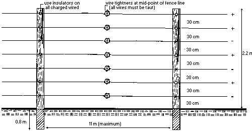
Figure 2. Electric fence configuration.
Braces
The fence must be well braced to withstand the pressure exerted on the corners and ends of the fence once the wires are pulled tight.
Use wooden 9 cm x 9 cm x 3 m braces at fence corners and at gates. Fence corners can be strengthened with an angle brace (Figure 3). This assembly sits inside the fence and slopes from the corner post to the ground at a 45 degree angle. Securely nail the angle brace to the post and rest it on a solid base at the ground. Secure the brace at ground level to the base of the corner post with several wraps of smooth wire, which are twisted tight with a "twitch" stick. This inexpensive brace is easy to install and works well.
Install a single span horizontal brace on each side of the gate (Figure 4). Position brace posts 3 m from each gate post and nail a horizontal brace between the top of each gate post and brace post. Fasten two wraps of smooth wire to the bottom of the gate post and near the top of the brace post, then twist the wire with a twitch stick to complete the assembly.
Gates
One or two gates can be built to move hay in and out of the yard (Figure 5). Space the gate posts 5.5 m apart. If spring gate assemblies are used, the gate can be electrified when it is closed. Install spring assemblies on each of the top six wires of the fence. Spring assemblies should be removed in the spring to prevent damage by livestock and the elements over the summer. Re-install them in the fall. As alternatives, an electrified gate of seven wire strands to match the fence or a high mesh gate can be built inexpensively. Non-electrified single or double span metal mesh gates can be purchased; however, they are expensive.
Wire
Wire can be strung on the outside of the fence once the posts and braces are in place. Use wrap-around insulators on all charged wires at end and corner posts (Figure 6). These insulators must be slipped on each charged wire before the wire is tied off. Move the wrap- around insulators along the wire to the appropriate corner post locations, then lightly staple them in place. Lightly staple ground wires at the corners to allow movement of the wires when they are tightened. Install line post insulators once the wires are in place and tied off (Figure 6).
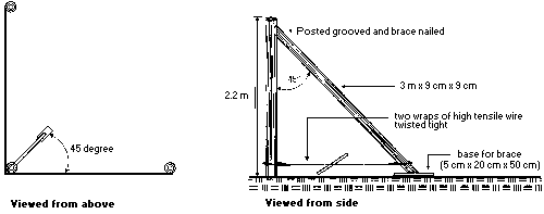
Figure 3. Corner brace assembly.
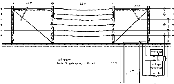
Figure 4. Gate and brace assembly.
Use compression sleeves on all wire connections and for tying off wires at end posts (Figure 6). Slip all the compression sleeves that will be needed on each line wire before tying off fenceline wires and move them to the appropriate locations on the wire. Compression sleeves are used to attach the power lead-out wire from the energizer to the charged fence wires, common wires (all charged wires connected together and all ground wires connected together), and the ground lead-out wire that connects the ground fence wires to the ground rod. Use two sleeves on all tie-offs and for any fenceline connections that are under tension.
A special crimping tool or bolt cutter with modified jaws can be used to crimp the compression sleeves (Figure 6). Proper wire splices made with compression sleeves are as strong as the existing wire. Figure-eight knots and screw clamps can also be used to make connections but neither of them are as strong as compression sleeves.
Install tighteners on each wire near the midpoint between the tie-offs. Some tighteners require cutting the wire for installation, others do not. Tighten wire from the top down. To reduce the strain on fence posts and brace assemblies, fence wires should be tightened after the ground is frozen in the fall and loosened again in late winter after the threat of depredation has passed.
Energizers
Electric fence energizers are available as 110 or 220 volt plug-in models or battery-operated units. Use a plug-in energizer because the battery-operated ones do not have enough energy to power the fence during extremely cold weather. Plug energizers directly into a power outlet. If an extension cord must be used, make sure it is a heavy gauge one. A long, light-gauge cord will create current resistance, affecting power output.
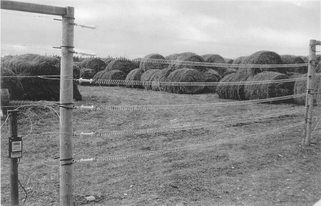
Figure 5. Spring gate assembly
If plug-in power is unavailable near the hay yard, string two single strands of fence wire on posts from a plugged-in energizer to the fence. One wire is charged and the other wire acts as the ground return wire from the fence to the energizer. In this case, use two 1.5 m ground rods at both the fence and the energizer to ensure proper grounding and maximum shock from the fence.
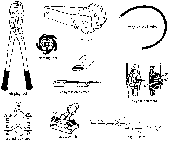
Figure 6. Fencing hardware
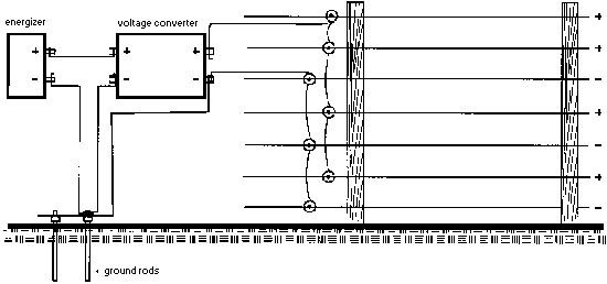
Figure 7. Energizer system hook-up.
An energizer designed for a short to medium length of fence, attached to a voltage converter, will provide the proper high voltage needed for a hay yard fence. Voltage converters substantially increase the voltage output of an energizer over a short length of electrified wire. The converter is especially helpful in winter when natural grounding conditions are poor due to the ground being frozen or snow covered. If a voltage converter is not used, a more expensive high output energizer will be needed.
To be effective, energizers must provide a large enough shock to elk or deer on their first contact with the fence to discourage them from making further attempts to enter. To discourage elk and deer from attempting to go through the fence in winter, the output of the energizer should exceed 7,500 volts between the charged wire and grounded wires of the fence. An animal touching both a charged and ground wire will receive the maximum shock. Any animal touching only a charged wire will receive a much smaller shock because of the poor conducting properties of snow and frozen ground, but the shock will be large enough to discourage further attempts at entry.
Hooking-up energizers
Attach a smooth wire from the ground wire terminals on the energizer and converter to the grounded wires of the fence and to two 1.5 m ground rods that are completely driven into the ground (Figure 7). The ground rods should be about 2 m apart. Attach the grounded wires to the ground rods with a ground rod clamp (Figure 6). Use a length of smooth wire to connect the charged wires of the fence to the power terminal (+) on the energizer. Use the same gauge and type of wire for the lead-out as for the electric fence.
When a voltage converter is used, connect the power terminal of the energizer to the power-in terminal of the converter. The power-out terminal of the converter is connected with a single wire to the charged wires of the fence. A cut-off switch can be installed in the power lead-out (Figure 6). The switch is handy for turning off the power during the day when equipment is in use around the hay yard.
Snow
If deep drifting snow makes it difficult to operate an electric fence, a snow fence may need to be installed on the upwind side of the electric fence.
Comparison of material costs to fence a one acre hay yard with electric fencing and mesh fencing (1999)
Materials | 7-wire electric fence | Exclusion mesh fence |
Amounts | Cost ($) | Amount | Cost ($) |
| Posts (10 ft.) | 26 @ $9.00 | 234.00 | 34@$9.00 | 306.00 |
| T-bars (10 ft.) | - | - | 42 @ $7.00 | 294.00 |
| High-tensile wire (100 lb ea) | 2 @ $74.00 | 148.40 | - | - |
| Mesh wire (330 ft/roll) | - | - | 3 @ $307.00 | 921.00 |
| Metal gate (20 ft x 7 ft) (double swing) | - | - | 1 @ $345.00 | 345.00 |
| Spring gate assembly | 6@$14.39 | 86.34 | - | - |
| Brace (10 ft x 4 in. x4 in.) | 6 @ $6.50 | 39.00 | 9 @ $6.50 | 58.50 |
| Staples (lb) | 3 @ $0.80 | 2.40 | 5 @ $.80 | 4.00 |
| Board (8 ft x 2 in. x 8 in.) | 1 @ $7.00 | 7.00 | - | - |
| Energizer (Baker 110 volt) | 1 @ $105.00 | 105.00 | - | - |
| Voltage converter (Baker 7707) | 1 @$42.50 | 42.50 | - | - |
| Ground rod (10 ft) | 2 @ $18.00 | 36.00 | - | - |
| Rod clamps | 2 @ $2.65 | 5.30 | - | - |
| Wire tighteners | 7 @ $3.10 | 21.70 | - | - |
| Tightener handle | 1 @ $6.15 | 6.15 | - | - |
| Crimp sleeves (100/pkg) | 2/pkgs @ $22.25 | 44.50 | - | - |
| Line post insulators (25/pkg) | 5/pkgs @ $2.22 | 11.10 | - | - |
| Wrap-around insulators (10/pkg) | 4/pkgs @ $12.89 | 51.56 | - | - |
 |  | $840.95 |  | $1,928.50 |
Please note prices will vary over time; these are 1999 figures.
Information prepared by
John B.Bourne, P.Ag.
2005
Source: Agdex 684-17. |
|